屋顶线模型roofline model
屋顶线模型是一种简化的、可视化的性能模型,用于快速判断程序是受 内存带宽 限制还是算术带宽 限制。
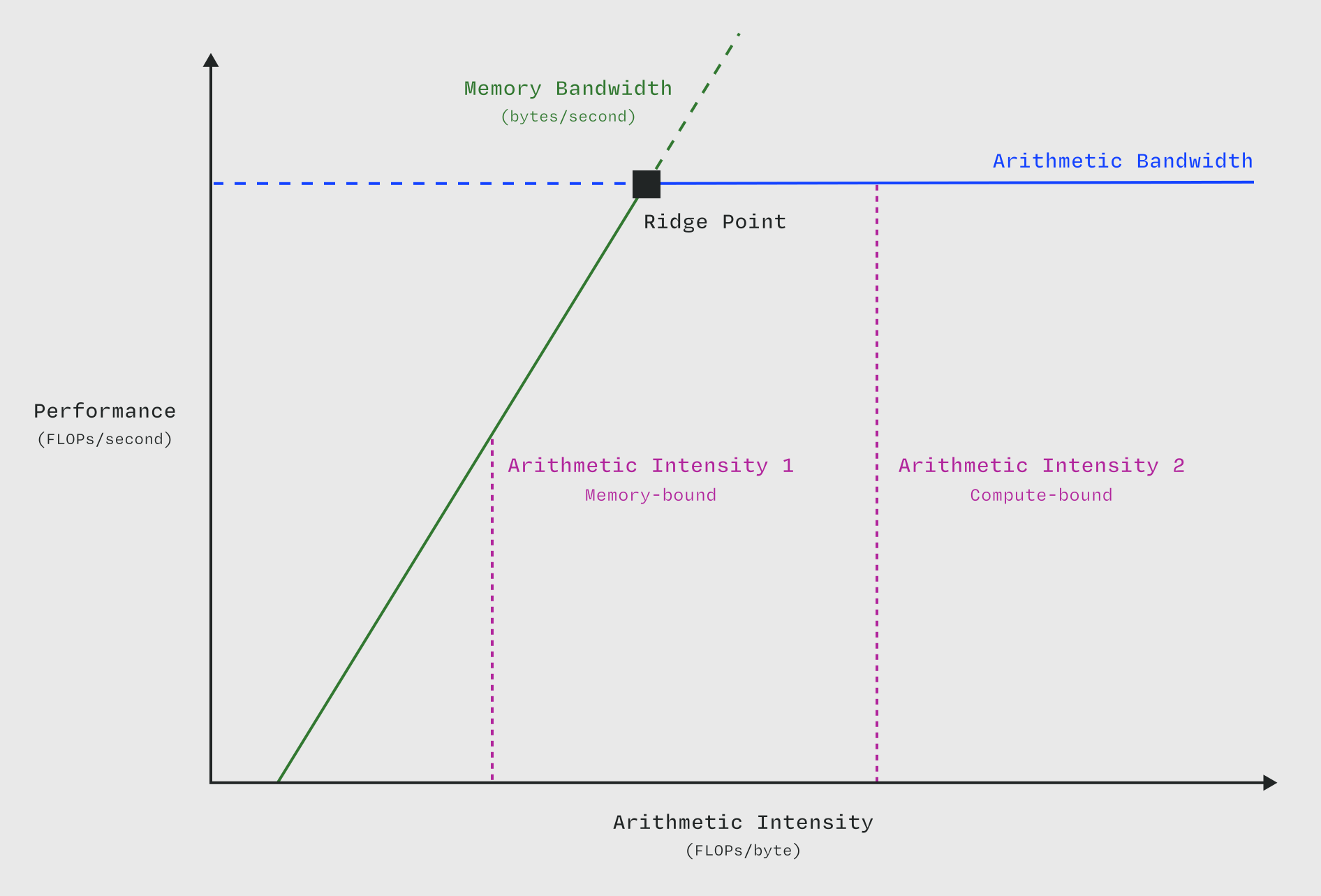
在该模型中,位于脊点左侧的 内核 受 内存子系统带宽限制,位于脊点右侧的 内核 时受 算术子系统带宽限制。图表改编自提出屋顶线模型的 Williams、Waterman 和 Patterson (2008)。
屋顶线模型中,两条由硬件特性决定的 “屋顶线” 构成了性能的上限:
将这些屋顶线绘制在一个平面上,其中 x 轴表示 算术强度(单位:操作数/字节),y 轴表示性能(单位:操作数/秒)。"计算屋顶线" 是一条水平线,高度等于 算术带宽。"内存屋顶线" 是一条斜线,斜率等于 内存带宽。斜率是 "垂直变化量除以水平变化量",因此该线的单位是字节/秒(即操作数/秒除以操作数/字节)。
通过某个 内核 的 x 坐标,可立即判断其本质上是 计算受限(位于水顶下方)还是 内存受限(位于斜顶下方)。由于 开销 的影响,[内核] (/gpu-glossary/device-software/kernel) 很少能真正触及这两条屋顶线。
屋顶线上的边界,即斜屋顶和平屋顶相交处,称为 "脊点"。其 x 坐标是摆脱内存 性能瓶颈 所需的最小 算术强度。脊点越靠左的计算机系统越容易实现最大性能;但随着时间推移,内存性能相对于计算性能的扩展速度较慢,导致系统的脊点普遍向右移动。
计算和内存屋顶线只需针对每个子系统推导一次(但需注意,它们因子系统而异,而非仅由系统决定;例如 张量核心 就比 CUDA 核心 具有更高的 FLOPS)。
NVIDIA 用于 内核 性能工程的 NSight Compute 工具在分析 内核 性能时自动执行屋顶线分析。
屋顶线模型看似简单,实则不然。例如,系统延迟并未出现在图表中的任何位置,仅包含带宽和吞吐量。它之所以简单,是因为它具有很强的倾向性,理解这些倾向性及其背后的原理是理解屋顶线模型的威力和正确应用的关键。
屋顶线模型由 Samuel Williams、Andrew Waterman 和 David Patterson 在 这篇 2008 年的论文 中提出。他们提出该模型时,硬件领域的几大趋势已深刻影响着系统架构的发展。
首先,正如 Patterson 在 2004 年一篇著名论文中单独观察到的,延迟的提升滞后于带宽。更具体地说,在计算、内存和存储等子系统中,延迟的线性改进历史上一直伴随着带宽的二次方提升。这表明未来的系统将像 GPU 一样,以吞吐量为导向。
其次,正如长期以来观察到的,计算子系统(如处理器核心)的性能扩展速度远快于内存子系统,如 缓存 和 DRAM。这在 1994 年被 Wulf 和 McKee 普及为 内存墙。
最后,21 世纪初,由于晶体管固定漏电流带来的功耗和散热问题,登纳德缩放比例定律(即在同等功耗下提高时钟速度)宣告终结。此前,提高时钟频率一直是CPU等通用延迟导向型系统性能提升的主要手段。而这一放缓并未伴随着 摩尔定律(即每芯片晶体管数量增加)的停滞。面对晶体管数量过剩但功耗受限的困境,硬件专业化成为架构上的解决方案:将计算机拆分为专注于特定任务的组件。关于一个记录详尽的例子,请参见 Pixel Visual Core 图像协处理器,该处理器在 Hennessy 和 Patterson 的第六版 _计算机体系结构_ 第 7 章中有详细解释。
综合这些趋势,作者们准确预测:未来的系统将以吞吐量为导向,并且在各种起作用的带宽中,内存子系统的带宽 将是主要的 性能瓶颈。因此,希望在这些系统上达到峰值性能的应用程序,应用程序需针对硬件的特定操作具备高运算强度——对于 GPU 而言,即针对 张量核心 的算术强度,也就是说需要执行大规模的矩阵乘法。
英文原文(Modal GPU Glossary)
The roofline model is a simplified, visual model of performance used to quickly determine whether a program is bound by memory bandwidth or arithmetic bandwidth.
to the left of the ridge point are limited by the bandwidth of the memory subsystem and kernels to the right of the ridge point are limited by the bandwidth of the arithmetic subsystem. Diagram adapted from Williams, Waterman, and Patterson (2008), which introduced the roofline model.](themed-image://roofline-model.svg)
In the roofline model, two hardware‑derived "roofs" put a "ceiling" on the possible performance:
- the "compute roof" – the peak rate of the
- target hardware (CUDA Cores or
- Tensor Cores), aka the
- arithmetic bandwidth
- the "memory roof" – the peak memory throughput of the target hardware, aka the
- memory bandwidth.
These are visualized on a plane with the arithmetic intensity (in operations per byte) on the x-axis and the performance (in operations per second) on the y-axis. The "compute roof" is a horizontal line with height equal to the arithmetic bandwidth. The "memory roof" is a slanted line with slope equal to the memory bandwidth. Slope is "rise over run", and so the line has units of bytes per second (operations per second divided by operations per byte).
A specific kernel's x-coordinate tells you instantly whether it is fundamentally compute-bound (points beneath the flat roof) or memory-bound (points beneath the slanted roof). Kernels are rarely up against either roof due to the effects of overhead.
The point on the boundary, i.e. where the diagonal and horizontal roof meet, is called the "ridge point". Its x-coordinate is the minimum arithmetic intensity required to be able to escape the memory bottleneck. Computer systems whose ridge point is further to the left are easier to achieve maximum performance on, but the relatively poor scaling of memory relative to compute generally has pushed the ridge points of systems to the right over time.
The compute and memory roofs need only be derived once per subsystem (though importantly they vary depending on the subsystem, not just the system; Tensor Cores have more FLOPS than CUDA Cores).
NVIDIA's NSight Compute tool for kernel performance engineering automatically performs roofline analysis for profiled kernels.
The roofline model is deceptively simple. Note that, for instance, system latencies do not appear anywhere in the diagram, only bandwidths and throughputs. It is simple because it is highly opinionated, and understanding those opinions and their reasoning is key to understanding the power and the proper application of the roofline.
The roofline model was introduced by Samuel Williams, Andrew Waterman, and David Patterson in this 2008 paper. They introduced it in the face of several hardware scaling trends that shaped system architectures before and since.
First, as Patterson separately observed in a famous 2004 paper, "latency lags bandwidth". More specifically, across subsystems like compute, memory, and storage, a linear improvement in latency has historically been accompanied by a quadratic improvement in bandwidth. This suggested that future systems would be, like GPUs, throughput-oriented.
Second, as has long been observed, compute subsystems (like processor cores) have scaled their performance much more rapidly than memory subsystems like caches and DRAM. This was popularized as the "memory wall" by Wulf and McKee in 1994.
Finally, the early 2000s saw the end of Dennard scaling, aka increasing clock speed at equal power, due primarily to the fixed leakage current of transistors, which posed power draw and heat dissipation problems. Increasing clock speed had previously buoyed general purpose, latency-oriented systems like CPUs, over special purpose hardware. This slowdown was not accompanied by a slowdown in Moore's Law, aka increasing transistor count per chip. The architectural solution to an abundance of transistors but scarcity of power was hardware specialization: disaggregating computers into components specialized in completing distinct tasks. For a well-documented example, see the Pixel Visual Core image co-processor, explained in detail in chapter 7 of the sixth edition of Hennessy and Patterson's _Computer Architecture_.
Taken together, these trends correctly suggested to the authors that future systems would be throughput-oriented and that among the various bandwidths at play, the bandwidth of memory subsystems would be the primary performance bottleneck. Applications of those systems that wanted to achieve peak performance would therefore need to have high operational intensity for that hardware's specialized operations — in the case of GPUs, arithmetic intensity for Tensor Cores, which is to say very large matrix multiplications.
相关词条
本词条改编自 Modal GPU Glossary(CC BY 4.0)· 中文翻译 miter6/gpu-glossary-zh,MAE 整理排版。